


Product classification
All-digital servo hydraulic press
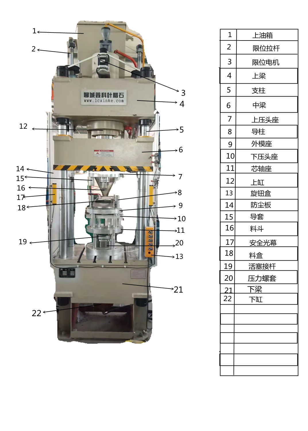
This machine is composed of two parts: the host and the control mechanism, which are connected by pipelines and electrical devices to form a whole.
- Product Description
-
Main technical parameters
NameName
UnitUnit
DataNumerical
RemarRemarks
Pressure
Main cylinder Nominal Pressure
KN
1200
Ejecting Nominal Pressure
KN
/
Max.liquid working pressure
Mpa
25
Stroke
Slide stroke
mm
500
Ejecting stroke
mm
/
OpeningHeigh
The max opening height
mm
900
The effective size o Worktable
Left to right
mm
700
Front to back
mm
620
Speed
Descending speed
Mm/s
80
Return speed
Mm/s
100
Machine total power
Machine total power
KW
Servo13.2
Voltage
Machine need Voltage
V
380
Inner diameter of cylinde
Inner diameter of the main cylinde
mm
/
Weight
Machine total weight
Kg
/
Structure and overview of the machine
Introduction for Equipment Structure
This machine is composed of two parts: the host and the control mechanism, which are connected by pipelines and electrical devices to form a whole. The structure and function of each part are described as follows:
The hydraulic press machine consists machine frame and control system two parts.The two parts are connected to a whole by connected line and electric installant.Each part of the machine is described as following:
1)Machine frame
The main engine of the hydraulic press is mainly composed of three beams (upper beam, movable beam and workbench) connected and fastened together through four columns (columns) and nuts to form an integral rigid frame to bear all the load of the hydraulic press. The parallelism of the corresponding surfaces of the movable beam and the workbench and the perpendicularity of the workbench plane to the piston of the main cylinder can be realized by adjusting the four adjusting nuts on the column under the upper beam. It has a good precision adjustment function. In order to ensure the precision of the machine tool can meet the use requirements, the connection between the column of the hydraulic press and the fastening nut, and the parallelism between the movable beam and the worktable must be checked and restored regularly according to the requirements.
The machine frame is made of the upper beam,moving beam and worktable.The upper beam,moving beam and worktable are connected to a overall rigidity work-frame by four column and nuts.The overall rigidity work-frame will bear all the load of the hydraulic press.The depth of parallelism between moving beam and worktable,and the verticality between the plunger of main oil cylinder and the worktable can be adjusted by four regulating nuts on the column under the upper beam.The accuracy of the depth can be adjusted as the need of the users.The connecting between four columns and clamp nuts and the depth of parallelism between moving beam and worktable must be checked and recovered as needed regularly.
2)The main cylinder
The master cylinder is the power conversion device of the machine tool. Hydraulic oil can be converted into functional pressure through the master cylinder. It is the heart part of the machine tool. The cylinder body and the piston rod are reliably sealed by rubber seals. All parts on the master cylinder are precision parts. Careful protection and maintenance are required. The rubber seal will be damaged due to aging after a period of time. It should be replaced by professionals in time to ensure its stable working efficiency.
The main cylinder is the power shifting device of the machine.The hydraulic oil can generate the needed pressure via the convert of the main cylinder.It is the heart part' of the machine.The gap between main cylinder and piston rod is reliably sealed by rubber sealing articles.All parts on the main cylinder are accurate parts.They need carefully protection maintenance.The rubber sealing articles can be worn out after a period of time,so please let professional staff check and exchange the sealing articles.making sure the stable working efficiency.
3) Ejection cylinder
A working cylinder installed in the workbench, the principle of action is the same as that of the master cylinder, and can achieve more actions in cooperation with the master cylinder to meet the needs of more complex processes.
The ejection cylinder is installed in one work cylinder of the worktable.it has the same work theory with the main cylinder.It works with the main cylinder to realize more actions.meeting the need of more complicated craft.It is the need of craft that determines whether the machine needs ejection cylinder or not.
4) Console Operating floor
The console can be moved freely within a certain range, and a two-hand operation structure can be set up to make the machine tool operate safely.
When working, the operator must press the button with both hands to lower the two ends of the operating system.
The operating floor can be moved optionally within the limits.It can be designed the two hands operation,making the operation safer.when working,the operator must press the down button ,the machine can act.
5) Stroke limit installation.
The travel limit device is located on the right side of the fuselage. It is a device designed for the position detection system of the machine tool and the automatic and semi-automatic work of the machine tool. It detects the action position or state of the machine tool, sends out an alarm or signal, and starts or stops the action of the machine tool.
The stroke limit installation is installed on the right side of the machine frame.It is the piston detector system of the machine.It is designed to realize the automatic operation and semi-autmatic operation.checking the action piston and condition of the machine.issuing warning and signal to warn the operation to start and stop the action.
6) Hydraulic pump station (power system) Hydraulic pump(dynamical system).
The hydraulic pump station is composed of an oil tank, an electric motor, a valve assembly, an oil pump, etc. It is equipped with air filters, level gauges and other devices. Its working principle provides a power source for the motor to drive the oil pump. It is driven by hydraulic valves and other driving devices (cylinders). Adjust and control the directional pressure to achieve various specified actions.
The hydraulic pump is made of oil-box,motor,valve ,pump and so on.it has the installation of air filter,liquid indicator and so on.its working principle is that the motor drives pump to provide the power source, through the hydraulic valve drive device for pressure regulation and control of action to achieve the various specific actions.
Key words:
Message consultation
Related Products


CONTACT US
Address: east of Luxi Orthopedic Hospital, Guangyue Road, Liaocheng High-tech Industrial Development Zone